Injection moulding is a widely used modern manufacturing, enabling the production of precise, high-volume plastic components through the injection of molten material into a mold cavity, where it cools and solidifies into the desired shape. However, injection moulding defects can compromise this process, manifesting as surface flaws or structural deficiencies that diminish part quality and elevate production costs.
These defects in moulding, such as flow lines, sink marks, and weld lines, arise from a complex interplay of factors including material properties, mold design, machine calibration, and process parameters. By addressing defects of plastic moulding through systematic injection moulding troubleshooting, we can mitigate issues like defect injection molding plastic.
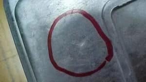
Flow Lines
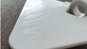
Flow lines are visible streaks or patterns on the surface of molded parts caused by uneven flow rates of molten plastic. They often appear due to low injection speeds or injection pressures that cause the resin to cool and solidify at different rates. Additionally, sudden changes in wall thickness or sharp corners can disrupt flow, contributing to flow lines.
Solutions for Flow Lines
- Increase injection speed and pressure to create smooth melt flow.
- Raise mold and melt temperatures to avoid premature solidification.
- Design parts with smooth transitions and rounded corners to minimize turbulence.
- Position gates in thin-wall areas for balanced filling.
- Select materials with lower viscosity or add flow enhancers to improve material movement.
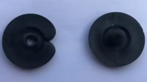
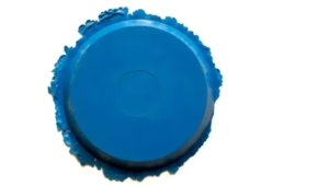
Sink Marks
Sink marks appear as depressions or dimples, usually on thicker sections of a part, caused by uneven cooling where the interior shrinks more than the outer surface. Improper packing pressure, brief hold times, or thick walls exacerbate the issue.
Solutions for Sink Marks
- Increasing packing pressure and hold time to better compensate for shrinkage.
- Design uniform wall thickness or reinforce thick areas with ribs.
- Increase packing pressure and holding time during molding.
- Optimize cooling channels for even temperature distribution.
Burn Marks
Burn marks are discolorations or dark spots caused by trapped hot gases or overheated resin degrading. They frequently result from insufficient mold venting, high injection speeds that trap air, and excessive melt temperatures.
Solutions for Burn Marks
- Improve mold venting to allow escaping gases.
- Reduce injection speed to avoid air entrapment.
- Lower melt temperature to prevent material degradation.
- Clean materials and equipment to remove contaminants.
Splay Marks

Splay marks, characterized by silvery or whitish streaks, emerge from moisture or contamination within resin flowing through the mold. Moisture turns to steam, creating these surface defects, often worsened by high shear rates and elevated temperatures.
Solutions for Splay Marks
- Dry materials thoroughly before molding to eliminate moisture.
- Lower melt temperature and reduce shear rates.
- Avoid contaminants during material handling.
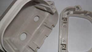
Surface Delamination
Delamination manifests as thin layers peeling off the surface, exposing underlying layers due to contaminants or overly aggressive mold release agents interfering with bonding. It can also result from incompatible or contaminated materials.
Solutions for Surface Delamination
- Ensure material purity and compatibility.
- Limit and optimize mold release agent use.
- Adjust mold and processing temperatures.
- Properly dry the resin to facilitate bonding.
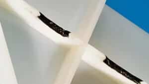
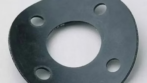
Weld Lines
Weld lines, or knit lines, occur where two melt fronts collide but do not fully fuse, creating weak seams visible on the part surface. These defects are typically found near holes or thin ribs where flows meet from different directions. Causes include low melt temperature, slow injection speed, and poor venting.
Solutions for Weld Lines
- Increase melt temperature and injection speed.
- Optimize gate placement for uniform melt flow.
- Improve mold venting to prevent air pockets.
- Add ribs near weld areas for strength.
- Selecting materials with lower viscosity
Shrinkage
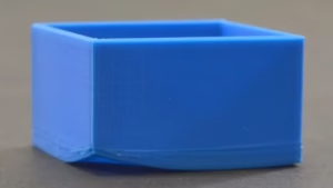
Shrinkage refers to overall dimensional reduction or localized contractions in the part after cooling. This occurs as the plastic transitions from melt to solid. Causes include short packing times that do not fill voids, rapid cooling rates, or high crystallinity in materials. Uneven wall thicknesses or inadequate compensation in mold design will intensified shrinkage.
Solutions for Shrinkage
- Prolong packing phase to stabilize shrinkage with additional material input.
- Design parts with uniform wall thickness.
- Control cooling rates through uniform mold temperatures to balance contraction.
- Design molds with 1-3 percent oversize cavities and ensure gradual wall transitions.
- Choose low-shrinkage resins, such as those filled with minerals.
Short Shots
Short shots occur when the mold cavity is not fully filled, resulting in incomplete or malformed parts. This typically results from low injection pressure or speed, blocked or undersized gates, trapped air, or insufficient mold venting.
Solutions for Short Shots
- Increase injection pressure and speed.
- Enlarge gates and runners for better melt flow.
- Enhance mold venting to release trapped air.
- Use low-viscosity materials to improve flow.
Warping
Warping causes parts to twist or bend due to uneven shrinkage stresses introduced during cooling. Non-uniform wall thickness and imbalanced cooling contribute significantly to warpage.
Solutions for Warping
- Maintain uniform mold temperatures and cooling channels for balanced shrinkage.
- Maintain uniform wall thickness.
- Extend cooling times to allow stress relaxation.
- Design symmetric structures with added ribs for rigidity.
- Apply post-molding annealing to relieve residual stresses.
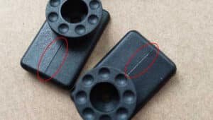
Jetting
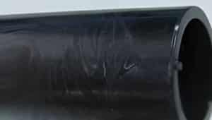
Jetting appears as snake-like or squiggly flow marks on the surface, caused when molten plastic enters the cavity too rapidly and begins solidifying before filling is complete. Small gate sizes, high injection speeds, and low mold temperatures often trigger jetting.
Solutions for Jetting
- Increase gate size and use fan or overlap gates.
- Lower injection speed to reduce melt velocity.
- Raise mold temperature to delay solidification.
Vacuum Voids
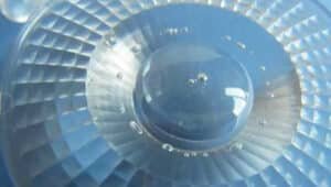
Vacuum voids are internal air pockets or bubbles trapped within the part. These form during shrinkage when gases cannot escape. Causes include inadequate packing pressure, fast cooling in thick sections, or poor venting.
Solution for Vacuum Voids
- Enhance packing time and pressure to occupy voids.
- Increase gate size and use fan or overlap gates.
- Lower injection speed to reduce melt velocity.
- Reduce wall thicknesses or use vacuum-assisted molding.
- Improve exhaust systems in the mold.
Discoloration
Discoloration involves uneven or altered coloring in the part, such as yellowing. This results from thermal degradation or impurities. Causes are high melt temperatures, prolonged residence times, or mixed materials.
Solutions for Discoloration
- Keep melt temperatures within recommended limits and shorten dwell times.
- Clean screws and barrels for pure material processing.
- Add stabilizers to resist oxidation.
- Ensure consistent color masterbatch mixing.
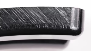
Flash
Flash is excess material along part edges from seepage through mold gaps. Causes include high injection pressure, worn molds, poor mold fit, or insufficient clamping force. Learn more about rubber flash.
Solutions for Flash
- Lower injection pressure and verify clamping force.
- Repair mold gaps.
- Optimize flow with reduced end-stage speed.
- Use high-precision mold materials.
- Avoid sharp corners at parting lines and maintain consistent wall thickness.
How to Identify Injection Molding Defects?
- Conduct visual inspections for surface patterns, colors, or marks using magnification or lighting.
- Perform tactile checks by feeling for roughness, bubbles, or deformations against standards.
- Measure dimensions with calipers or coordinate measuring machines for shrinkage or warping.
- Run functional tests under stress or environmental conditions to reveal weak points like weld lines.
- Use instruments such as ultrasound for internal voids or thermal imaging for uneven heat traces.
- Track batch records to correlate defects with process parameters for predictive identification
The Relationship Between Defects and Costs
Injection moulding defects lead to increased scrap rates, material waste, rework labor, and scrap disposal, escalating manufacturing costs and reducing profitability. Indirectly, they cause delays in delivery schedules, potential penalties from clients, and damage to reputation, which can lead to lost business opportunities. In defects in plastic moulding, unresolved issues may increase overall expenses due to halted lines or additional quality controls. Effective troubleshooting in injection moulding minimizes these effects, preserving profitability and efficiency.
Zhongren Leverages DFM Expertise to Prevent Injection Moulding Defects
At Zhongren, comprehensive injection moulding troubleshooting and Design for Manufacturing (DFM) strategies are employed to anticipate and eliminate defects early. By optimizing part design, mold engineering, and process parameters, Zhongren guarantees superior quality and cost-efficient defect injection molding plastic solutions tailored to client needs.