Cooling injection molding refers to the process of heat removal in injection molding operations. This stage involves solidifying the molten plastic material inside the mold cavity after injection. Cooling in injection molding ensures that the plastic part achieves the required shape and properties before ejection. The cooling phase typically occupies 50 to 70 percent of the total cycle time in injection molding processes. Without proper cooling, the plastic may not solidify uniformly, leading to inconsistencies in the final product. Optimizing cooling systems will enhance efficiency, maintain dimensional accuracy, and shorten cycle times.
Basic Structure of Cooling Systems
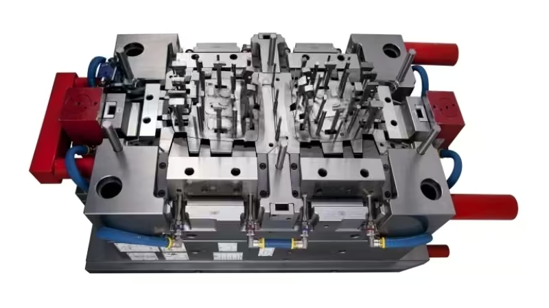
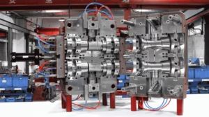
The foundation of a cooling system in injection molding lies in its structural components, which work together to ensure effective heat transfer.
Cooling Channels
Cooling channels are passages drilled or formed within the mold plates to allow coolant circulation. These channels are positioned close to the mold cavity, typically 10 to 15mm away, to maximize heat transfer while maintaining mold strength. Their layout depends on the part geometry, with complex molds requiring intricate channel designs. Proper channel design also relates to the overall injection moulding working principle, as it directly affects part cooling and cycle efficiency.
Manifolds and Fittings
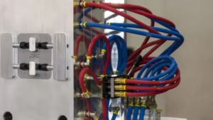
Manifolds distribute coolant evenly to multiple channels within the mold, ensuring consistent flow rates across all circuits. They are typically made of corrosion-resistant materials like stainless steel to withstand prolonged exposure to water or oil. Fittings, including quick-connect couplings and hoses, link the manifold to the coolant supply and return lines. High-quality fittings prevent leaks, which could disrupt cooling or contaminate the workspace. Manifolds are designed with multiple ports to accommodate various channel layouts, and their sizing must match the pump capacity to avoid pressure drops.
Baffles and Bubblers
Baffles and bubblers are specialized components used to enhance coolant flow within the mold. Baffles are flat plates inserted into channels to create a zigzag flow pattern, increasing turbulence and improving heat transfer efficiency. They are often used in larger molds to ensure uniform cooling across wide areas. Bubblers, on the other hand, are tubes that direct coolant into deep or narrow core sections, such as those in tall bosses or ribs. Coolant flows up through the bubbler tube and out around it, cooling areas that standard channels cannot reach effectively. These components are suitable for complex geometries where standard channels alone are insufficient.
External Temperature Control System
Although not part of the mold itself, the external temperature control system is a vital component of the cooling system in injection molding. It functions together with other molding processes such as insert molding services, where temperature stability is essential for bonding metal and plastic parts effectively.
- Pumps: Pumps circulate the coolant through the channels at a steady flow rate, typically 1 to 3 meters per second. This ensures consistent heat removal across the mold.
- Temperature Control Units: Temperature control units regulate the coolant temperature to prevent thermal fluctuations. These units include heaters and chillers to adjust the coolant within specified ranges, ensuring stable mold conditions throughout production.
- Sensors: Sensors monitor temperatures at various points in the mold and coolant system. This data allows operators to adjust flow rates or temperatures during operation, ensuring consistent injection mold cooling performance.
- Pipes and Valves: These connect the external system to the mold, directing coolant flow.
Cooling Technologies in Injection Molding
The injection mold cooling process can be categorized into machine-level cooling and mold-level cooling. In the following content, we will explore the two cooling technologies.
Injection Molding Machine Cooling Methods
Injection molding machines require dedicated cooling systems to maintain operational temperatures. The injection molding cooling for the machine focuses on components like the barrel, hydraulic systems, and electrical enclosures. Two primary methods are employed: air-cooled systems and water-cooled systems.
Air Cooling System: Air-cooled systems use fans to blow ambient air over heat-generating parts. This method is straightforward and involves minimal infrastructure, making it suitable for smaller machines or low-heat applications. Air cooling relies on convection to dissipate heat, with fins often added to increase surface area. However, its efficiency decreases in high-temperature environments or during prolonged operations, as it cannot achieve precise temperature control.
Water Cooling System: Water-cooled systems circulate chilled water through dedicated channels or heat exchangers within the machine. This approach provides superior heat removal capabilities, allowing for consistent temperatures even under heavy loads. Water cooling is common in larger injection molding setups where precision is necessary. The system includes chillers to cool the water, ensuring it absorbs heat effectively. Additives like glycol may be mixed with water to prevent corrosion or freezing.
Different Types of Injection Mold Cooling Systems
The mold itself employs specific cooling techniques to solidify the plastic part. Injection mold cooling designs include straight-line cooling and conformal cooling systems.
Straight-Line Cooling: Straight-line cooling channels are the traditional and simplest cooling mold design. These channels are drilled in straight lines parallel to each other inside the mold plates, often used for parts with flat or simple geometries. They are easier to manufacture and maintain, but may not provide optimal cooling for complex shapes or thick parts because the coolant flow and heat transfer are limited to linear paths.
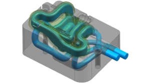
Conformal Cooling: Conformal cooling gives a more advanced approach where cooling channels conform closely to the shape of the part geometry. This design follows the contours of the mold cavity, allowing even and more effective heat extraction from all areas. Conformal cooling channels reduce cycle time significantly and improve the uniformity of part cooling, minimizing warpage and defects. This technique, often produced using additive manufacturing technologies like 3D printing, is highly beneficial for complex or intricate parts but comes with increased tooling costs and design complexity.
Design Principles for Cooling Systems
Effective injection mold cooling design follows several key principles to optimize performance and ensure high-quality production.
Uniform Heat Removal
Cooling channels must be arranged to remove heat evenly across the mold surface. Uneven cooling leads to hot spots, causing defects like warping or sink marks. Simulation software models heat flow to optimize channel placement for balanced temperature distribution.
Channel Diameter and Spacing
Channels typically have diameters of 6 to 12 millimeters, selected based on coolant flow requirements. Spacing ensures adequate coverage without overlapping or weakening the mold. Channels are placed 3 to 5 millimeters from the cavity surface to maximize efficiency while avoiding structural risks.
Flow Dynamics
Turbulent flow is preferred over laminar flow to increase heat transfer coefficients. Baffles or varying channel cross-sections promote turbulence. Coolant velocity, usually 1 to 3 meters per second, is adjusted to achieve optimal flow conditions.
Material Selection
Mold materials like aluminum or beryllium copper inserts enhance cooling efficiency due to high thermal conductivity. Steel is used for durability in high-volume production. The coolant type—water for general use or oil for high temperatures—must align with the application’s thermal needs. These design choices are also influenced by the requirements of custom molded plastics, where part complexity and material properties determine cooling performance.
Integration with Mold Design
Cooling channels should not interfere with ejector pins or other moving parts. Quick-connect fittings for coolant lines simplify maintenance. The design must balance cooling efficiency with mold functionality and longevity.
Common Issues with Cooling Systems
Improper cooling system design or operation leads to several problems in injection molding. These issues affect part quality, cycle time, and equipment longevity.
- Non-Uniform Cooling: Uneven cooling occurs when heat removal varies across the mold. This results from poorly placed channels or inconsistent coolant flow. Consequences include warping, where the part distorts due to differential shrinkage. Sink marks appear on surfaces as thicker sections cool more slowly. Residual stresses may cause cracking over time.
- Inadequate Cooling: Insufficient cooling happens when heat extraction is too slow. This extends cycle times, reducing production rates. Parts may eject while still soft, leading to deformation.
- Excessive Cooling: Excessive cooling involves overly rapid heat removal. This can make parts brittle by inducing rapid solidification. Over-shrinkage may occur, affecting dimensional accuracy. Adjusting the coolant temperature upward prevents this.
- Condensation: In humid environments, low mold surface temperature can cause condensation on the mold surface, affecting part finish and mold maintenance.
Conclusion
The cooling system in injection molding, encompassing structured components, advanced technologies like conformal cooling, and precise design principles, ensures efficient heat removal for high-quality production. Addressing issues like uneven or insufficient cooling minimizes defects and optimizes cycle times. Zhongren provides professional injection molding services, leveraging advanced cooling technologies to guarantee efficiency and quality in production projects.